
- G353A049
- ASCO
- 0097
- Aluminium
- 0.35~0.85 MPa
- -10~70 ℃
- C113686
- NBR
- 2.5 inch
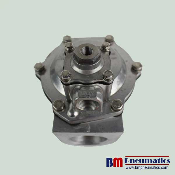
1. Product Name: G353A049 ASCO 2.5″ Air control Remote pilot Pulse jet valve Double diaphragm valve
2. Specificaton
| pipe size | orifice size | flow coefficient Kv | operating pressure differential (bar) | catalogue number | OPTION FPM | |||
| mln. | max. (PS) | |||||||
| air | ||||||||
| (mm) | (m3/h) | (l/min) | -/= | standard | ATEX II2G/D | |||
| G – Threaded pipe connection | ||||||||
| 1 1/2 | 52 | 46 | 768 | 0,35 | 8,5 | G353A046 | G353A046 GD | V |
| 2 | 66 | 77 | 1290 | 0,35 | 8,5 | G353A048 | G353A048 GD | V |
| 2 1/2 | 66 | 92 | 1540 | 0,35 | 8,5 | G353A049 | G353A049 GD | V |
| 3 | 76 | 170 | 2833 | 1,0 | 6,0 | G353-058 | G353-058 GD⑴ | V |
3. General
Differential pressure (PS) 0,35 – 8,5 bar [1 bar = 100kPa]
Ambient temperature range -40/-20 to +85°C (TPE/CR)
4. Construction
Body: Aluminium
Spring: Stainless steel
Diaphragm: TPE (thermoplastic polyester elastomer) or
CR (chloroprene)
5. Features
1. The diaphragm pulse valves are especially designed for dust collector service applications, combining high flow, long life and extremely fast opening and closing to provide reliable and economical operation
2. The high flow, angle type bodies in combination with the special main diaphragm assemblies give the unique operating features required for dust collector service applications
3. Integral compression fittings for fast, easy, secure installation
4. Valves can be supplied according to ATEX Directive 94/9/EC for non-electrical equipment by using suffix GD
5. The components satisfy all relevant EC directives
7. Spare parts kit and replacement coils are available